A true dobson with an old tube
The essence of a true Dobson
What is the main characteristic of a Dobson telescope?? The response to this question is that a Dobson telescope is moved by hand (not gears, no mechanics stuff), and that this movement has a special “touch”: neither too soft nor too hard; using the same force both to start the movement as to keep it; letting go of a star drift easy and accurately…
A Dobson telescope there is not a true Dobson if theirs movements aren’t as described in the last paragraph, so the only manner of recognizing a true Dobson is to move it.
Be careful about web pages when the author seem to talk about make a Dobson. Usually, the author make anything that SEEM to be a Dobson and LOOKS like a Dobson… but if the author don talk about the special movement of a Dobson, perhaps is because there is not a true Dobson.
Controlling the friction
The secret for the special movement characteristics of a Dobson telescope flow from a design when the friction in both altitude and azimuth axes is taking into account.
My main font about how to calculate the friction of a Dobson comes from the book “The Dobsonian telescope: A Practical Manual for Building Large Aperture Telescopes”, by D. Kriege & R. Berry (thanks to Pablo Canedo for talk me about this book).
Using the right materials
A lot of materials was tested by experienced people, finding for the right material to use in order to get the necessary friction. The static and dynamics friction coefficient must be similar. The friction must be higher enough for compensate tremors, inertia or wind effects, and small enough for can move the telescope in an easy manner.
Unless you know exactly what you’re doing, you must use virgin Teflon and some concrete laminate models as frictional material. For this combination of materials, the static friction coefficient is 0.10, and the dynamic one is 0.08, according the “Kriege & Berry” book.
These recommended laminates are both “Ebony Star #4552” from Wilsonart Inc. and “Stardust #1782” from Formica Inc. Perhaps some other laminates will work, but you MUST use one of these for ensure the correct friction.
The force to move the tube depends on the position of the Teflon pads, and the these forces must be similar in both axes. On the other hand, the position of the pads don’t must affect to the stability. So the position (and size) of the Teflon pads must be calculating carefully.
The main parameters to consider are the weight of some parts. One is the weight of the complete tube, including the side bearings. Let label this weight “p”. The second is the weight of the complete tube (including the side bearing) plus the rocker box (without the ground board). Let label this weight “P”.
Calculate the force necessary for move the telescope
For make a design that match the before considerations,we must calculating the forces that is necessary for moving each axis (altitude and azimuth). These calculations are specified in the following diagram, made by “pulgaril”, a member of the “Constructores de telescopios” Yahoo group (http://es.groups.yahoo.com/group/ConstructoresTelescopios/)
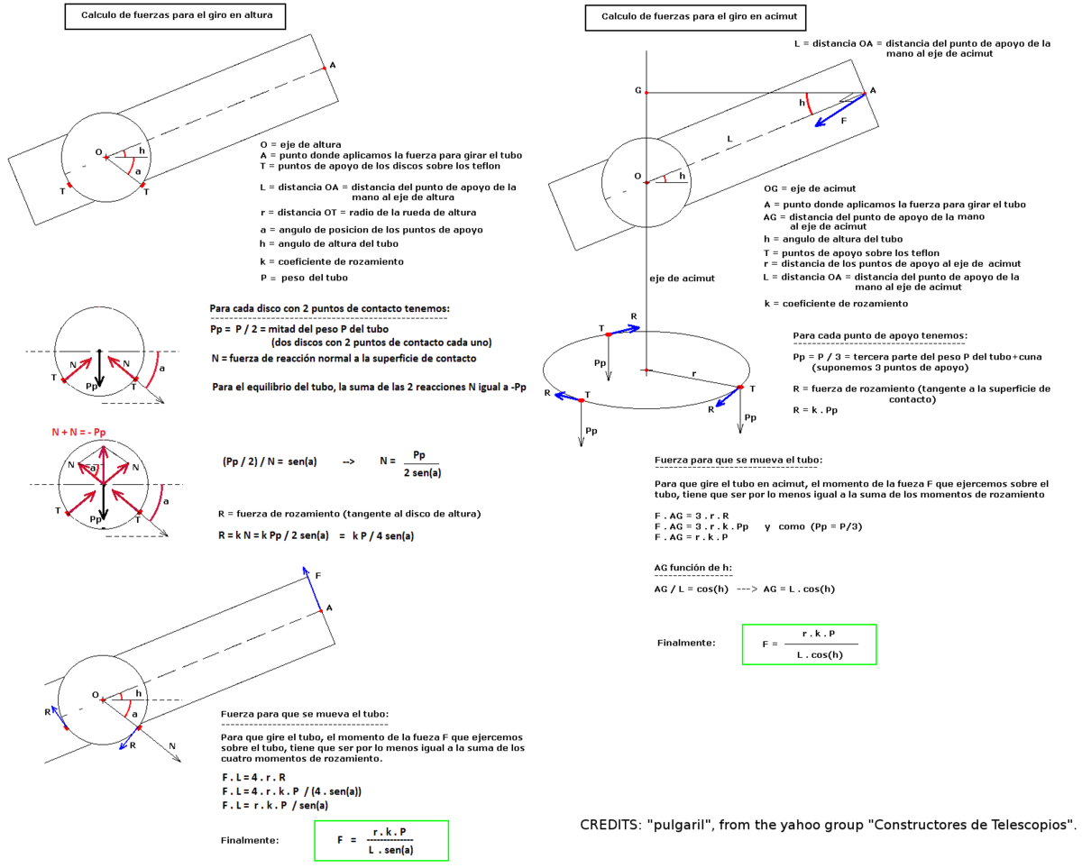
Axis forces
We have for the altitude axis:
Fa = [r * k * p] / [L * sen(a)]
Where:
“r” is the ratio of the altitude bearings.
“k” is the friction coefficient.
“p” is the weight of the tube plus the tube support with bearings.
“a” is the angle between the horizontal and the position of the altitude Teflon pads.
“L” is the distance from the bearing centre and the point when you hold the tube for move it.
And for the azimuth axis:
Fz = [R * k * P] / [L * cos(h)]
Where:
“R” is the distance between the pivot to the Teflon pads of the azimuth axis.
“P” is the total weight of the tube plus the tube support with bearings plus the rocker box.
“h” is the altitude where the tube points to.
The others coefficients are the same that in the altitude axis case.
Designing a Dobson
Now, we have the mathematical expressions that can help us for design a dobson telescope. Never the less, there are more parameters that equations, so we can’t calculate all the design parameters we need.
To avoid this difficulty, we use a double approach.
First, we fix some of these parameters according to empirical values recommended by experienced Dobsons constructors or to a compromise value.
This empirically fixed parameters are:
“k”, the friction coefficient is determinate by the material used. If we use, as experience said, Teflon and one of the recommended laminate, the value of this parameter will be the adequate one. From “Kriege & Berry” book, this value is 0.08.
“a” is the angle between the horizontal and the position of the altitude Teflon pads. The “Kriege & Berry” book talk about the empirical separation of the two Teflon pad for each bearing must be 60 degrees, so the angle between the vertical and each pad will be 30 degrades, so the angle “a” must be 90-30=60 degrades.
“h” is the altitude where the tube points to. Obviously, this parameter varies when we are using the telescope… the solution to this issue is use a value for “h” that will be approximately the more usual one. The experienced observer report that this value is 60 degrades.
Second, we will use and iterative method for tune the design. Firstly, we make a very first design an according to it, we will ESTIMATE the values of “L” (distance from the bearing centre and the point when you hold the tube), “p” (tube plus bearings weight), “P” ( p plus rocker box weight) and “R” (distance between the pivot to the Teflon pads of the azimuth axis).
When you have estimated all this parameters, you can CALCULATE the last parameter “r” (the ratio of the altitude bearings). This can be calculated by equate both the forces necessary to move the tube both in altitude and azimuth axis.
This diagram show the flux of estimating and calculating:
   +·······················································+
   ·                                                       ·
   ·  +-------------+   +-------------+   +-------------+  ·
   ·  |  ESTIMATE   |   |  ESTIMATE   |   |  ESTIMATE   |  ·
   ·  |             |   |             |   |             |  ·
   ·  |  Tube plus  |   |  Tube plus  |   |  Pivot to   |  ·
   ·  |  altitude   |   |  bearings   |   |  azimuth    |  ·
+---->|  bearings   |-->|  (p) plus   |-->|  teflon     |-----+
|  ·  |  weight (p) |   |  rocker box |   |  pads       |  ·  |
|  ·  |  and the    |   |  weight (P) |   |  distance   |  ·  |
|  ·  |longitude (L)|   |             |   |     (R)     |  ·  |
|  ·  |     (1)     |   |     (2)     |   |     (3)     |  ·  |
|  ·  +-------------+   +-------------+   +-------------+  ·  |
|  ·                                                       ·  |
|  +·······················································+  |
|                                                             |
|                      +---------------+                      |
|                      |   CALCULATE   |                      |
|                      |               |                      |
|                      | Ratio of the  |                      |
+----------------------| altitude      |<---------------------+
                       | bearings (r)  |
                       |               |
                       |      (4)      |
                       +---------------+
                              ___
                               |
                               | Break the
                               | loop
                               |
                              `'
               +------------------------------+
               |           CALCULATE          |
               |                              |
               | Pivot to azimuth teflon pads |
               | distance (R)                 |
               |              (5)             |
               +------------------------------+
More details in estimating “L”, “p”, “P”, “R” and calculating “r” in the following subsections.
When the tube, the bearings and the rocker box was building, you can weight the real things… and you can now calculate (instead estimate) the pivot to azimuth teflon pads distance (R).
More details in calculating “R” in the following subsection.
(1) Estimating tube plus bearings weight (p) and the longitude (L)
We must make a very first design of the tube and the altitude bearings. As a first approximation, we can use a size for the bearings equal to the mirror size. There are no magic in this: but we need a first value.
By using the density of the used materials, and calculating the amount of it, we can estimate the weight “p”. Estimate “L” is immediate from the design, and, probably, it must not be changed from iteration to iteration.
As the end of the iteration, we will calculate a new bearing size, so a new “p” value must be estimate…
(2) Estimating tube plus bearings weight (p) plus rocker box weight (P)
Analogue to the before point, by using the density of the used materials, and calculating the amount of it, we can estimate the weight of the rocker box. This weight plus the value “p” from the before point, will produce a value for “P”.
As before, after a complete iteration, we will calculate a new bearing size, so “p” value change and, consequently, the “P” value also must be re-estimated…
(3) Estimating pivot to azimuth teflon pads distance (R)
As a first approach, our first design must have the “legs” of the ground board as separate between them as possible. In this way, all the structure is as stable as possible. The azimuth teflon pads must, ideally, lay just where the legs of the ground board (but, evidently, in the other side). This rule have us a first value for the “R” parameter.
This value “R” must not be changed between different iterations, and, ideally, it must not be changed in the final design.
But, in practical, a final re-calculation of “R” must be done AFTER break the loop. See subsection about the calculating of “R” for more about this.
(4) Calculating the ratio of the altitude bearings (r)
For found an expression for calculate “r” (the ratio of the bearings), we can equate both altitude an azimuth axis force. This is:
Fa = Fz => [r * k * p] / [L * sen(a)] = [R * k * P] / [L * cos(h)] =>
=> r * p / sen(a) = R * P / cos(h) => r = [R * P * sen(a)] / [p * cos(h)]
And, by using the assumed values for “a” (60 degrees) and “h” (also 60 degrees), we can write:
r = [R * P * sen(60)] / [p * cos(60)] => r = [R * P * 1.73205] / p
By using this last equation, we can calculate a new value for the ratio of the bearings (r), and continuing the loop…
(5)Break the loop: calculating pivot to azimuth teflon pads distance (R)
In practical, a final re-calculation of “R” must be done AFTER break the loop.
This can be necessary by different factors. Perhaps is not possible an arbitrary size for the bearings (if we use some precast material for it, for example); or simply, AFTER construct the tube, bearing and rocker box, we note that our estimations about the weight was very bad ones.
So, after we have been build the tube, bearing, and rocker box, we have now a fixed value for the weights “p” and “P” and for the bearing ratio “r”. And a final tuning must be done before build the ground board. For this tuning, we will new calculate (instead estimate) a definitive value for “R”, the distance between the pivot and the azimuth teflon paths…
This can be done with the following equation:
r = [R * P * 1.73205] / p => R = [r * p] / [P * 1.73205]
Please note that, due the considerations about structure stability commented before, the new calculate “R” value should not be very different from the first estimated one, according with the cited considerations.
An, if we must change a little the positions of the azimuth teflon pads, perhaps we must also reconsider repositioning the legs of the ground board for put it just in the opposite side that the teflon paths. In this way, we reduce the vibrations, especially is the telescope is a big one…
Calculating teflon pads sizes
theoretically, the friction DON’T depends on the area of contact of both materials. But in “Kriege & Berry” book they claims that the area of contact between both teflon and laminate should have a concrete value, determined empirically from the experience of advanced Dodson constructors. These value can be consulted in 3.5 table from the book.
In this table, according the materials used, the pressure (weigh by area unit) is listed. For the usual materials (teflon and laminate), this value must by, according the authors, 15 PSI (pounds per square inch). In the metric system this is equivalent to 0.0105462 Kg/mm2 (10.5462E-3 Kg/mm2).
Please note: theoretically the friction between materials don’t depends on the area of contact. Never the less, I agree with that for some unknown (for me) reason, we MUST respect the “Kriege & Berry” book criteria and use the correspondent area of contact.
Due the considered pressure value, and the weights, calculate the teflon pads sizes is easy.
And, as last note, the force necessary for move the tube in both axis should be about 0.15 ~ 0.20 Newtons. For a value of this force too low or too big, perhaps you could consider a drastic redesign, or the use of nylon instead virgin teflon, as suggested in the “Criticism and lessons learned” subsection of the case study part, later in this document.
Teflon pads size for the altitude axis
Let me show how to make the calculation for the altitude teflon pads by using an example.
If the tube plus bearings weight is, for example, 15.5 Kg the TOTAL area for the needed teflon will be:
15.5 / 10.5462E-3 = 1470 mm2
But for the altitude axis we must use 4 teflon pads, so for EACH altitude teflon pads the area must be:
1470 / 4 = 367.5 mm2
Now, one of the dimensions of the teflon pads will be equal to the used wood thickness (suppose it is 15 mm), so the other dimensions of the teflon pad will be:
367.5 / 15 = 24.5
So, for the example, the size for each one of the 4 altitude teflon pad could be 15 x 24.5 mm
Perhaps these values can be improved by take in account some issues as a possible hole for screw them to the wood or some cut down in the sides that attack the laminate in the direction of movement (this is, the sort sides). But this tuning is a problem of elementary geometry.
Teflon pads size for the azimuth axis
In a similar manner, the size for the pads of the azimuth axis can be calculate. But here there are to possibilities: the simple case, with 3 square teflon pads, and an enhanced case, with 3 square pads plus a tiny circular pad around the central pivot hole.
The enhanced case with central pivot teflon pad is recommended for hight weight (related to the wood thickness used for the bottom part of the rocker box).
For both possibilities, the very first step is calculate the TOTAL area for the need teflon. As an example, lets consider a weight for the tube, plus bearings, plus rocker box of 21 Kg, so the total area must be.
21 / 10.5462E-3 = 1991 mm2
Now, the methodology for calculation are a few different for the simple case (3 teflon paths) or the engagement one (3 teflon pads plus a central pivot pad).
Simple case (3 pads)
Due we have 3 pads, the area for each of them must be:
1991 / 3 = 663.7 mm2
and, due we considered square pads, the size for each side must be:
SQRT(663.7) = 25.8 mm
So, for the example, the size for each one of the 3 azimuth teflon pads would be 25.8x25.8 mm. As in the previous case, the calculation can be improved by take in account a possible cut down for the teflon pads, now in all the sides.
Engagement case (3 teflon pads plus a central pivot pad)
For this case, we must subtract the area of the central pivot pad before calculate the size of the 3 square ones. As an example, consider a central circular pad of 15 mm of radius and a pivot hole of 10 mm of diameter (5mm of radius), so instead use the total area of used teflon (1991 mm2), we subtract the area of this circular pad:
1991 - [PI * (15^2 - 5^2)] = 1363 mm2
And the following calculations are similar to the simple case, but use this modified total area, so the area of each each square pad would be:
SQRT(1363 / 3) = 21.3 mm
So the squared pads size would be 21.3x21.3 mm
As in the previous case, the calculation can be improved by take in account a possible cut down for the squared teflon pads (and maybe in the circular one), in all the sides.
Please note that the presence of a central pivot pad don’t change the calculation of the force for the azimuth axis. This is because the pivot pad MUST be small, so the distance of every superficial points of the pivot pad is near 0 apart the pivot itself, so them can be obviated in the practice. A small size for the pivot pad is also necessary for maintain the size of the square pads not too few.
So be careful: a central pivot pad always must be small…
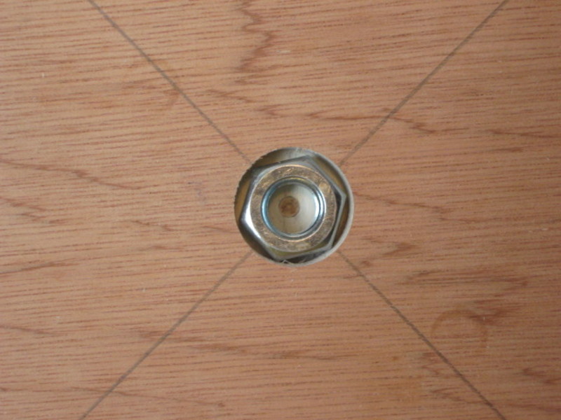
The azimuth pivot
The “Kriege & Berry” book talk about the making of the azimuth pivot in extent. I refer to the book if you are planning a Dobson.
Never the less, I design my own azimuth pivot. My design only have value when the thickness of the wood used for make the ground board is about 1.5 or 2 Cm.
In this design, a “packing ring” like piece of thin (about 0.2 mm) virgin teflon is adhered surrounding the pivot hole at the rocker box (at top side). The ground board is worked for embed a nut in the manner showed in the correspondent section of the case study part.
The pivot components are also showed at the case study part of this document, and its description is the following:
A M10 screw has adhered a packet ring in its head. This packet ring has also adhered a thin teflon sheet at side opposed to the head of the screw. A piece of teflon tape is applied to the body of the screw, from the head to a length that must be equal to the thickness of the wood used for make the rocker box. The hole for the pivot at the rocker box should be lined with a piece of steel pipe.
Other pieces of the pivot are: a free “packet ring” of thin teflon, a “packet ring” of felt, a normal steel packet ring and a nut.
Once the pivot is mount, this is the list of all components, in the order its lies:
The head of the screw.
A steel packet ring adhered to the head of the screw.
A thin packet ring made of teflon, adhered to the before metal packet ring.
A free thin packet ring made of teflon.
A thin packet ring made of teflon, adhered to the top of the rocker box.
The bottom of the rocker box.
The ground board. The ground board has a embedded nut.
A free packet ring made of felt.
A steel packet ring.
A nut. This last nut product a countersunk effect with the other embed in the rocker box.
When the pivot is in the corresponded site, the countersunk effect must be adjusted. The force between the teflon pads fixed to the ground board and the laminate fixed to the rocker box must be near zero, but without clearance. A periodic readjustment of this stuff is recommended.
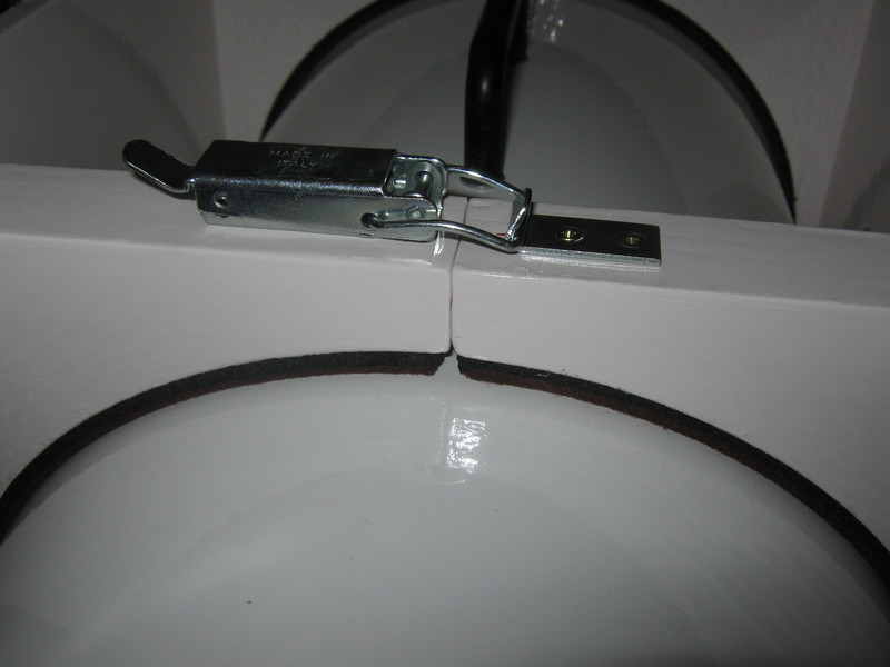
=====================================================================
A case study: refurbished old newton tube
My very first Dobson experience was aborted based on a old Newton 200mm tube.
My goal was learn about the dobson mount and use the this old tube for star-hopping technique with Dobson telescope (until then I always used a equatorial telescope for star-hopping.
I don’t intend a detailed description of the work, but only show it and present ideas that I hope become useful for other people.
The bearings
My idea was to attach the tube to the bearings by using pressure The device used for attach the altitude bearing to the tube is easily released from the it in order to place the tube easily in a convenient manner for balancing it or put the eyepiece in the best side depending on the sky zone we are observing.
The bearing themselves are formed by two 20cm diameter PVC pipe caps. Star-dust ribbon is adhered in the frictional surfaces of the bearings by using epoxy adhesive.
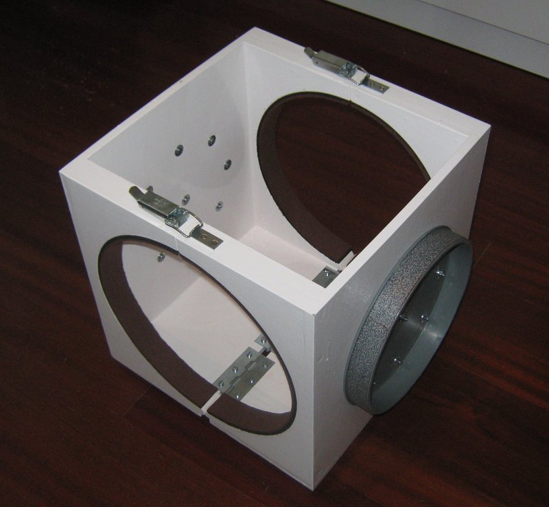
bearings close
Here the bearings attached to a device that can be fixed to the tube. The bearings are 20 cm diameter, with an skin of Stardust. A soft material is used when the device contact with the tube. A mechanism permit a easy relaxing the device from the tube for fine tuning of its position.
bearings open
Here the device that support the bearings opened for introduce the tube and attach it.
bearings on rocker
Here the bearings presented in the rocker box.
bearings lock
Thus mechanism permit easily fix and relax the device to the tube.
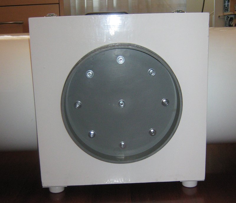
bearings side
This is the lateral side of the bearings, fixed to the device and with the tube attached. Note the little legs that permit put the structure on the floor.
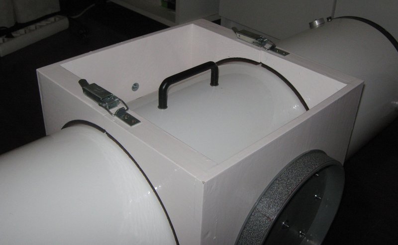
bearings with tube
This perspective show the tube attached to the bearings.
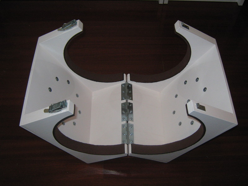
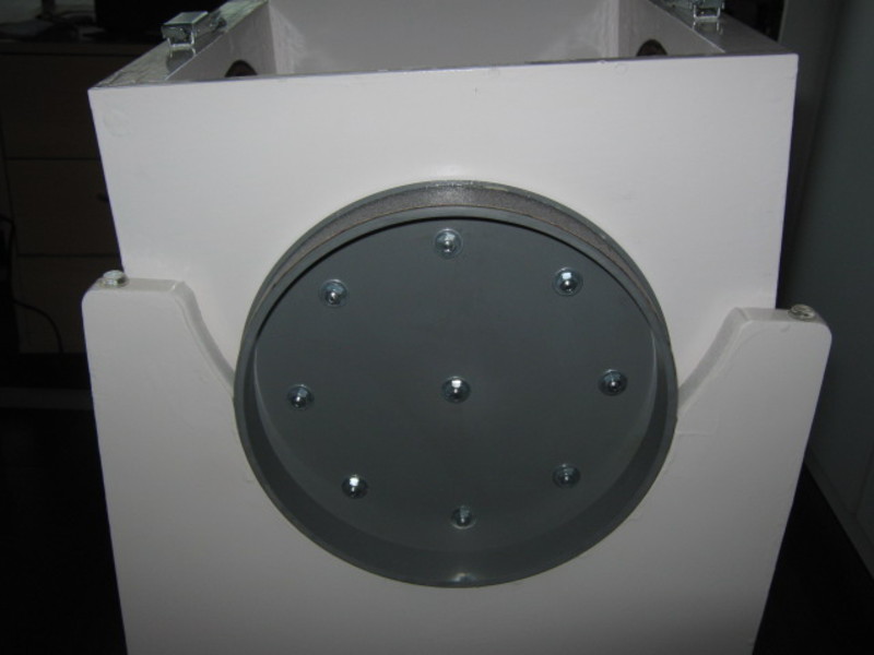
The rocker box is conceptually simple, but it must be resistant and made with
precision, specially the semicircles when the bearings will lie.
Please note the special feature for support the tube in order to adjust the placement between the tube and the device that support the bearings.
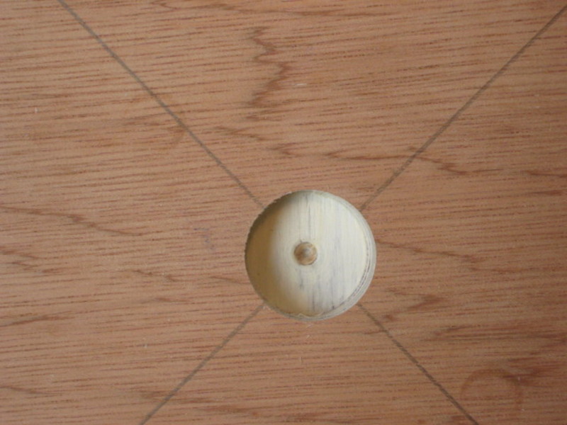
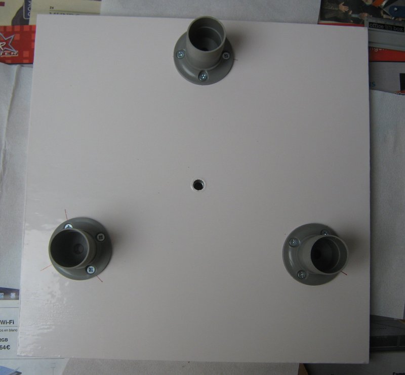
In the down, the rocker box has a hole for the azimuth pivot.
The stardust surface is adhered by use contact cement. There are contact cement of different viscosity. You should use one with low viscosity.
A guide must be used for align the rocker pivot hole with the laminate hole for the pivot. The laminate must be bigger that the rocker base. When the adhesive run dry, the excess of laminate can be rasped.
After the rocker box was completed, a thin adhesive felt was added for avoid accidental damage of surface when the bearing is placed.
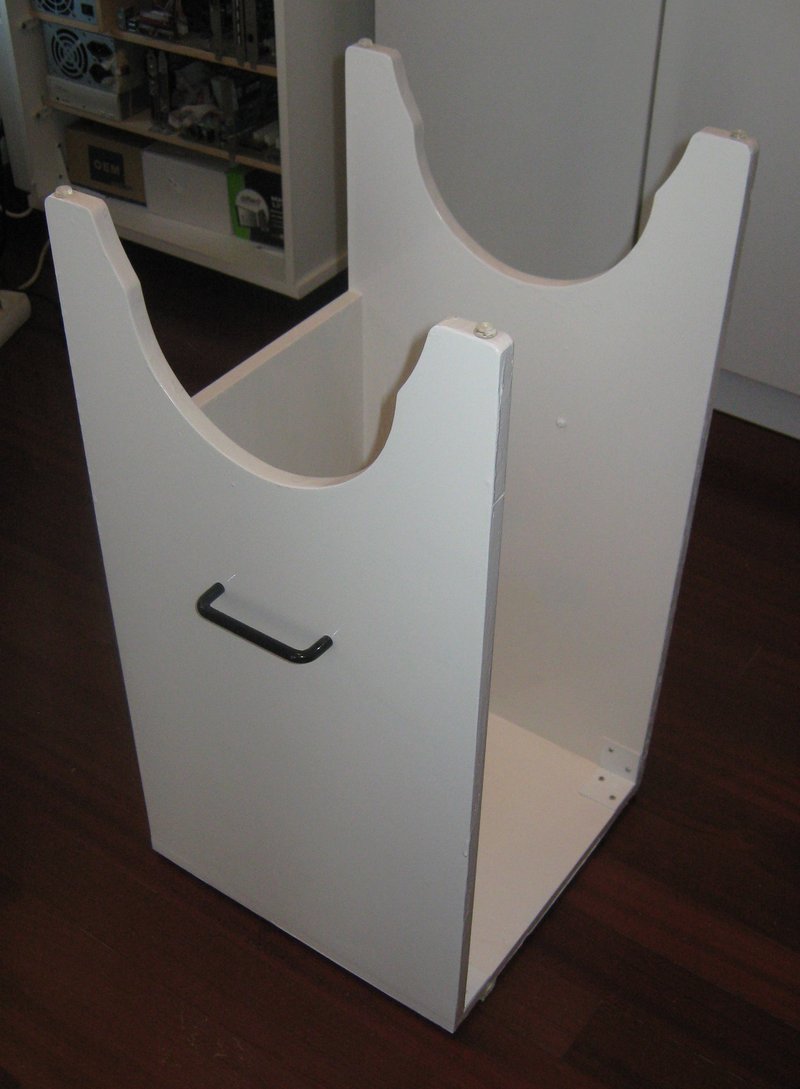
rocker perspective
A perspective of the rocker box.
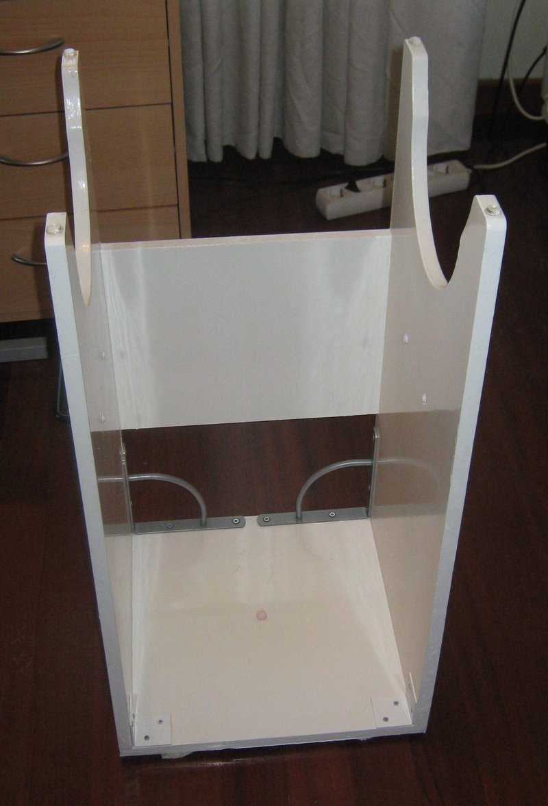
rocker front
Here we can appreciate the rocker box structure.
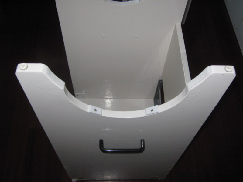
altitude both teflon pad
The altitude teflon pads attached to the rocker box. They are 60 degrees apart
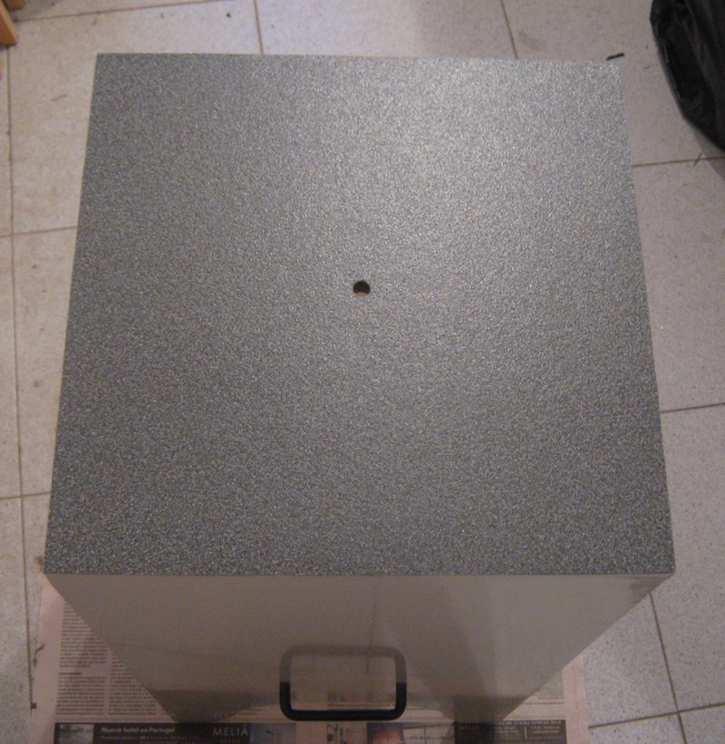
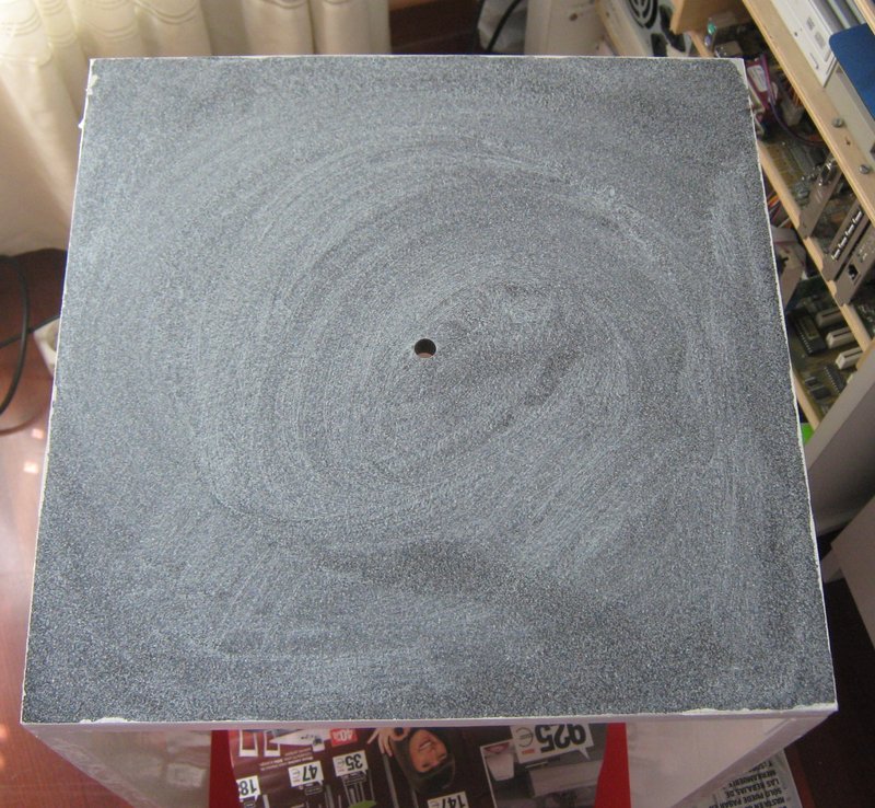
rocker down
The Stardust base adhered to the bottom of the rocker box.
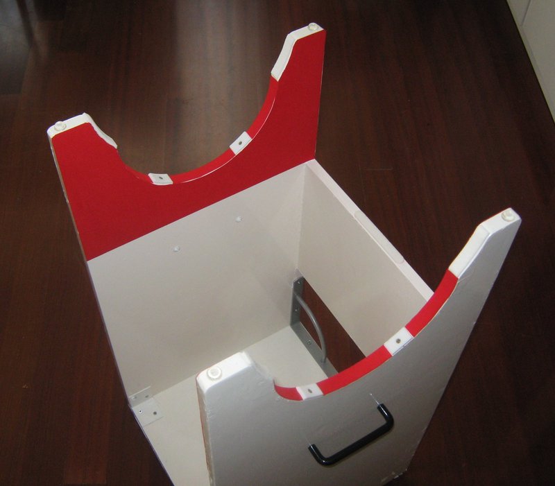
rocker with adhesive felt for protection
The finished rocker box. A adhesive protection was added.

tube on rocker
Here we can see how the tube can be hold by the rocker box, for and easy tube manipulation and setup…
The ground board concept is really simple. The only difficult is to put a nut
in the right manner for the azimuth pivot and mark the position for the teflon azimuth pads and for the foots.
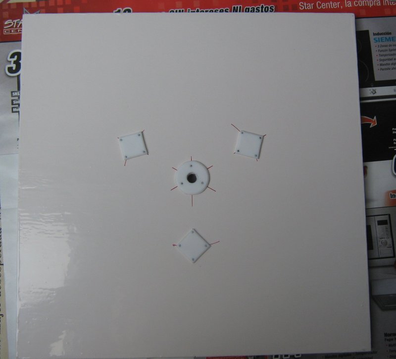
For mark the position for the teflon azimuth pads and for the foots, we will use cardboard templates, made accord with our calculations.
The nut for the pivot is punting as showed in the pictures. Please note that for a more resistant mount, the foots must be put in the same side when the nut was aligned, and the teflon pads in the other.
For a optimal stability and resistance, the foots must be put in the manner that they was at the most distance one of another, and the teflon pads must be over the foots, in the other side of the ground board.
Please note that THIS LAST POINT IS NOT ACCOMPLISHED in my design This WAS CAUSED BY A ERROR DESIGN I must improvise a compromise solution for maintain the force to manage the azimuth axe about similar to the altitude one.
ground board preparation 1
This partial hole was done with an adequate Forstner drill.
ground board preparation 2
The nut must fit in the partial hole.
ground board preparation 3
With a normal drill, the hole is completed as showed.
ground board preparation 4
The nut is fixed by using an epoxy based putty.
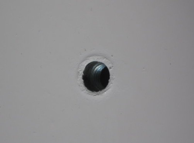
ground board hole for pivot
The close part of the hole if reinforced by fits a piece of steel pipe.
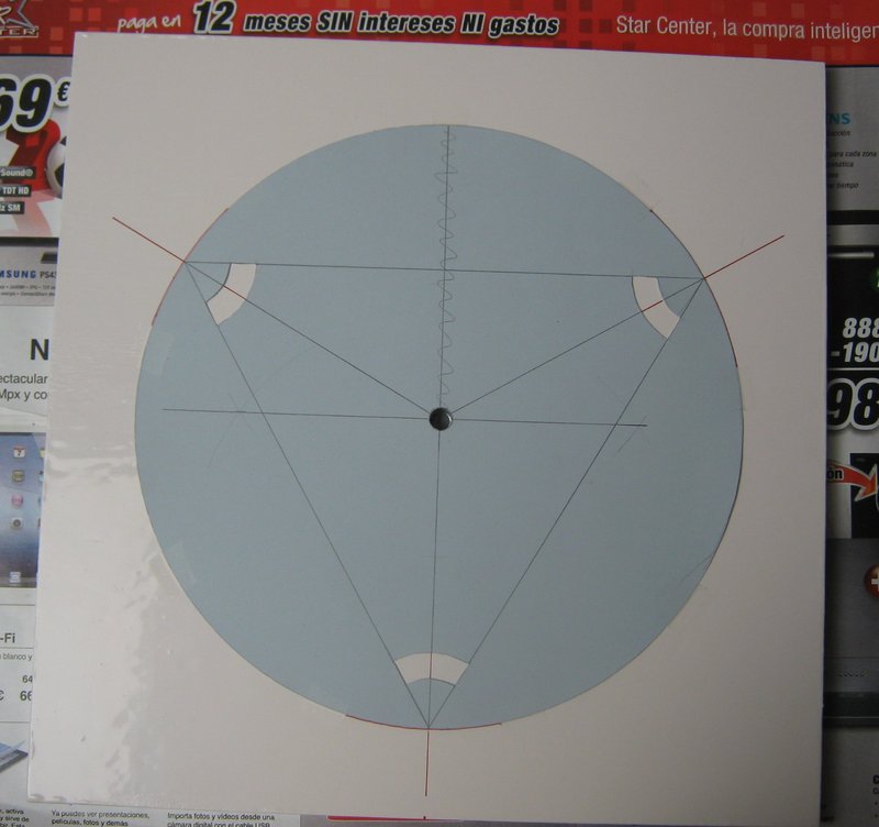
template mark foots on ground board
This carton template was used to mark the holes for screw the legs of the ground board.

mark foots on ground board
Here the position for the screws of the legs are marked.
foots on ground board
And here, the legs of the ground board.
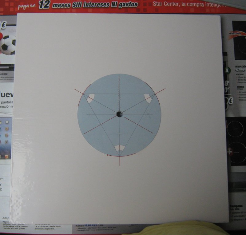
template mark for teflon pads on ground board
Other carton template was used for mark the position of the azimuth teflon pads.

mark for teflon pads on ground board
The marks for the azimuth teflon pads in the right position.
ground board
Here, the finished ground board.
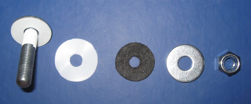
Teflon pads
The teflon pads size was calculated in the manner described before. For the altitude teflon pads a hole was drilled for use a screw for keep it in place. The contact surface missing by this hole and by some reduction of material in the shorter sides was considered when the size of pads was calculated
For hold the altitude teflon pads in their places we will use screws as showed in the pictures. The screws heads must be buried into the teflon pads. It is very important that the head of the nails don’t touch the laminate when it slide over the teflon pads.
For hold the azimuth teflon pads, a double sided adhesive ribbon plus tiny nails was used. The nails heads was buried inside the pads by using a punch. It is very important that the head of the nails don’t touch the laminate when it slide over the teflon pads.
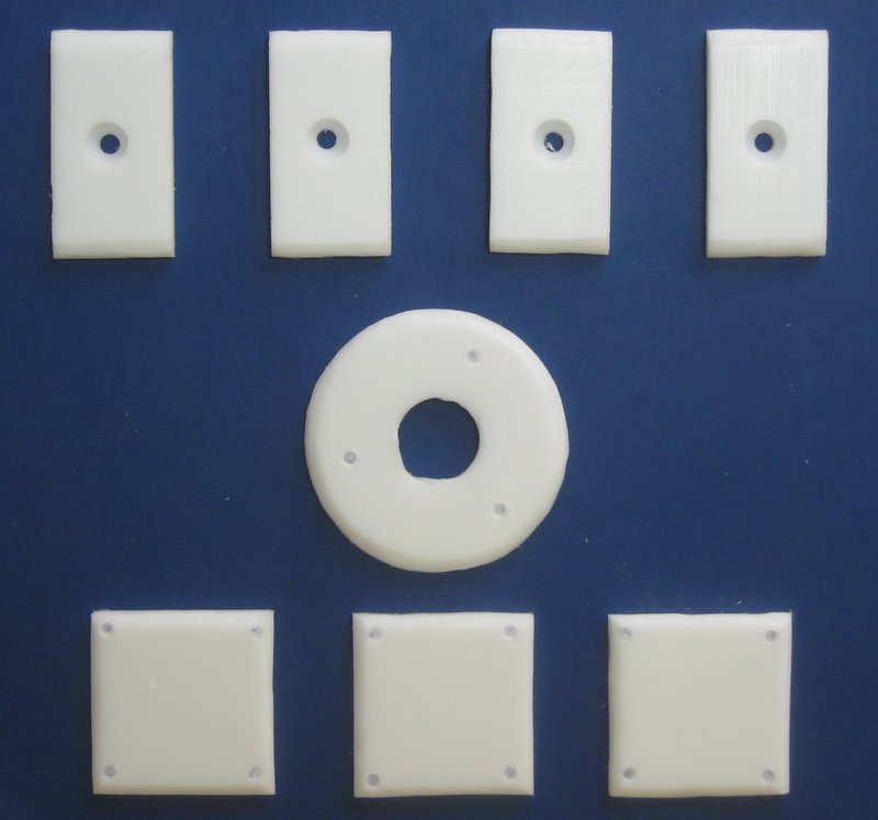
teflon pads
The teflon pads. The four altitude teflon pads at up, the azimuth ones are the others.
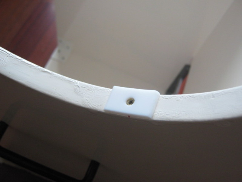
altitude teflon pad
Detail of one of the altitude pad.
teflon pads on ground board
The azimuth pads.
The Pivot
pivot components
The pivot components are showed in the picture.
Car wax for better performance.
For a better performance, car wax was applied to the laminate. It must be extended by using a cotton cloth. After it dry, remove the rests with a brush.
In the picture, the rocker laminate is showed after wax was applied and dry. It must be brushed until no wax rest were appreciate.
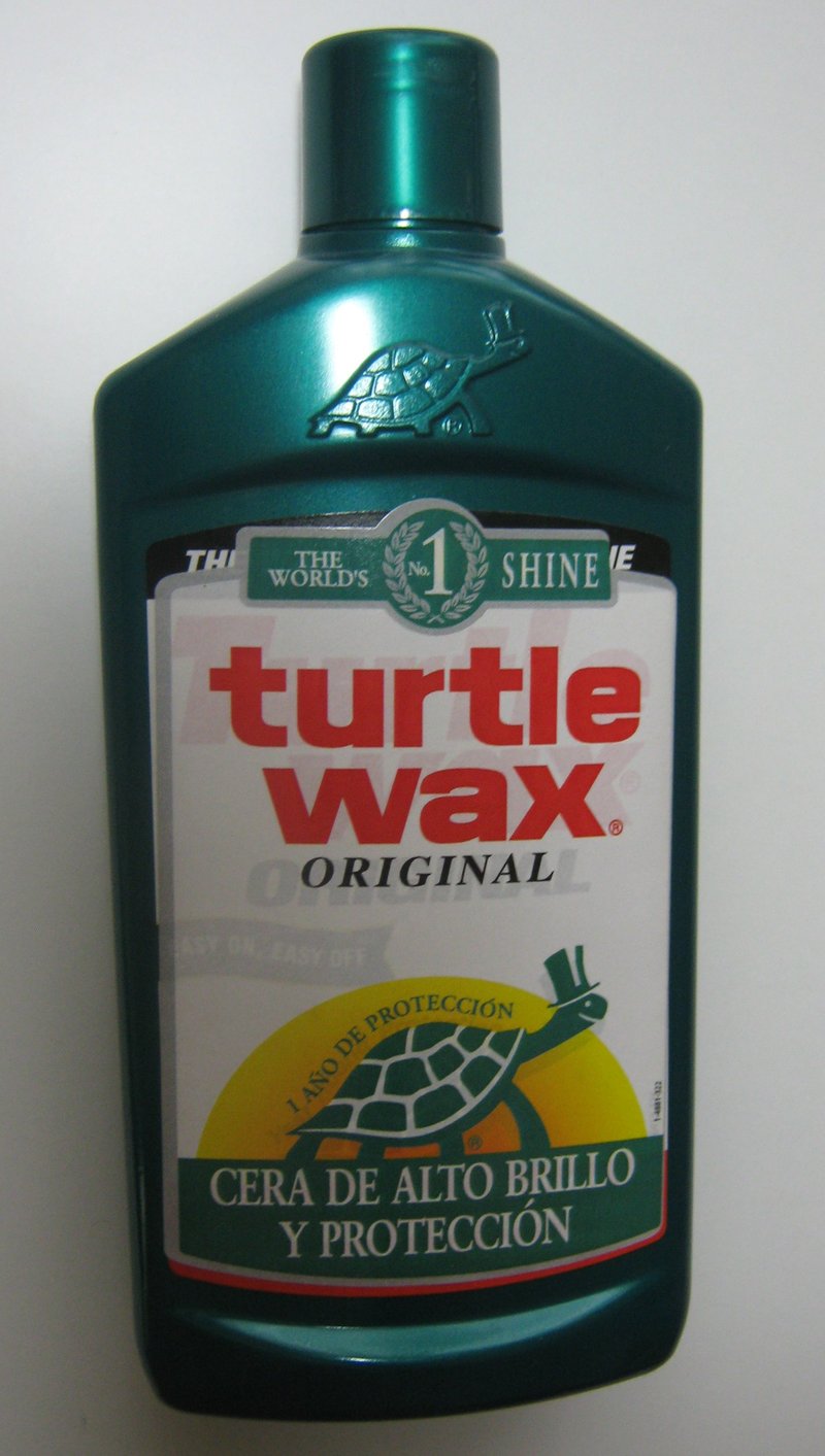
turtle wax
The car wax used for optimize performance.
turtle wax on stardust unbrushed
Here can be seen the StarDust after the application of the car wax. The next steep must be to brush the laminate after the car wax was dry.
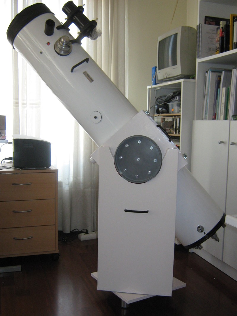
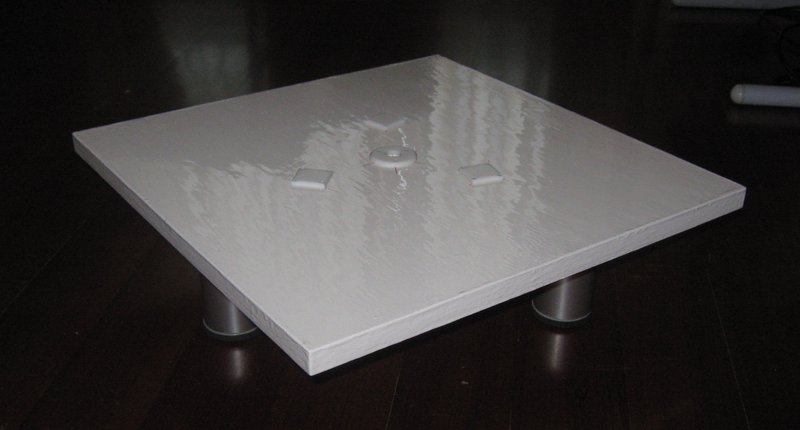
result
This picture show the Dobson telescope finished.
Car integration
For a portable telescope, the integration with the car is very important. The following pictures show how the telescope is transported in my car. An ad-hoc device made with a thermal insulation material used in construction and some plastic ribbons is used for maintain the telescope in place.
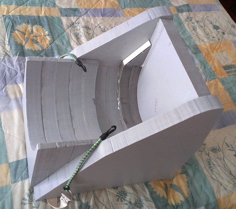
aict
This device is used for integrate the telescope with the car for transportation. It was made by using a thermal insulation material used in construction.
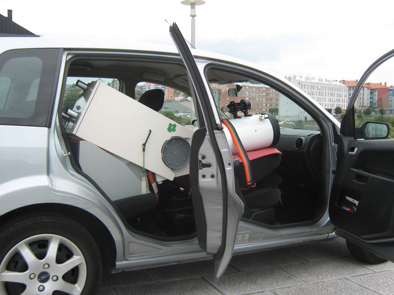
result in car
This picture show the telescope integrated with the car.
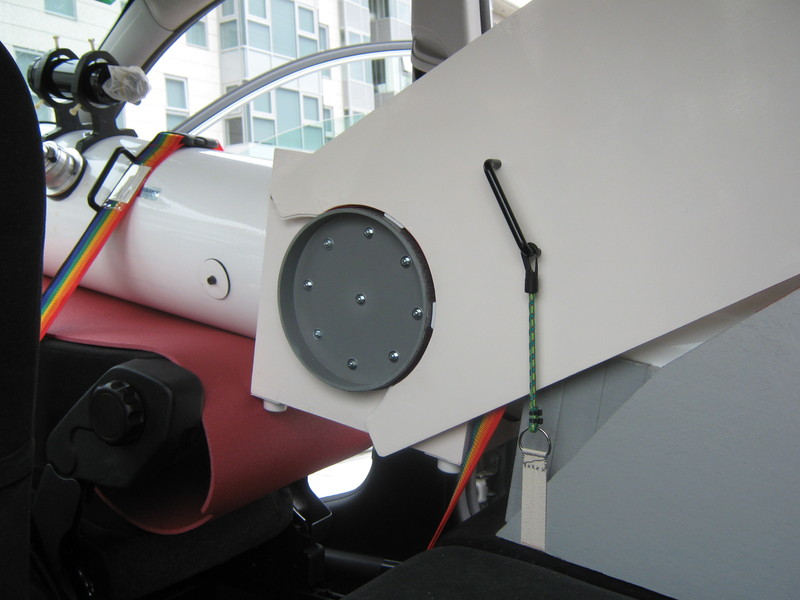
result in car detail 1
The tube is hold by two cinch. The Rocker box is hold to the device where the tube lies by two elastics ribbon, one to each side.

result in car detail 2
The ground board is fixed to the rocker box by a elastic ribbon for transportation.

result in car detail 3
In my car, the copilot seat can be swing: perfect for the transportation.
Criticism and lessons learned
There are two failures in my telescope.
One is that the rocker box is 5 cm too taller. It was an implementation error, not a design error. I added twice the 5cm extra, necessary for make the appendices for hold the tube by the rocker box. Due this error, the rocker box just fit in my car: too just… It also increases slightly the vibration of the rocker box.
The other error is an authentic design error: the distance from the pivot hole to the squared teflon pads in the ground board (R) is too small. Some people ask me: Why simply do you put them more separate from the central pivot? The answer to this question is that if I did that, then the force necessary for move the tube in the azimuth axis would be too weak, and very different to the force necessary in the altitude axis: this is precisely the situation that I want to avoid.
The reason that a standard design does not work for this particular telescope is that the tube is heavier than it would be a typical truss one (for a same aperture).
For the case of a heavy design (a tube heaver than the truss one equivalent or a very big tube in any case) like the mine, the value “r” should be bigger for make the correspondent value of “R” big enough, and the forces in both axis approximately equal. But then, the value of these forces can be too low. For avoid this issue, you can consider using nylon instead virgin teflon to make these values greater. This is because the friction coefficient for the nylon is greater (0.19 dynamic, 0.20 static) that for the virgin teflon.
So a correct design for my telescope should have bigger bearing, so the distance from the pivot to the azimuth teflon pads could be big enough to make them be near the edge of the ground board. In this manner, the structure should be stable, and the forces to move the tube in both axis should be approximately equal. But these forces can be too small; so, in this case, we can use nylon instead teflon for make the pads…
Never the less, when I was aware of these errors, the work was almost over… so I decide continue with the design, but using a “R” a few bigger that the theoretic value and close a few the legs of the ground board. In this manner, I got an not-so-worse stability…
When I tested the telescope at country, in a real observation, the results was good, even due the cited errors… I am happy with the result and I learned a lot making the work.
Clear skies.